Guide · Plan and model
From a 2D floor plan to a 3D model: start a project
Use a floor plan to define the layout and a 3D view to inspect the same building from another angle. Start with one floor and a small scope. Check dimensions before adding detail.
1. Start with an underlay and a known dimension
Open the project drawing and choose a floor. Use a drawing image or PDF as an underlay if you have one. The image alone does not create walls or rooms.
Use the scale adjustment tool. Select both ends of a known distance and enter its actual length. Choose a long, clear dimension. An incorrect scale gives incorrect quantities even when the outline looks neat.
2. Draw the elements needed for your work
Add walls, openings and rooms. Check wall thickness, heights and door and window sizes. Give rooms names that you will recognise in quantity lists.
You do not have to draw everything at once. For a renovation, start with the area covered by the job. Add other floors and elements when reliable information is available.
3. Inspect the same project in 3D
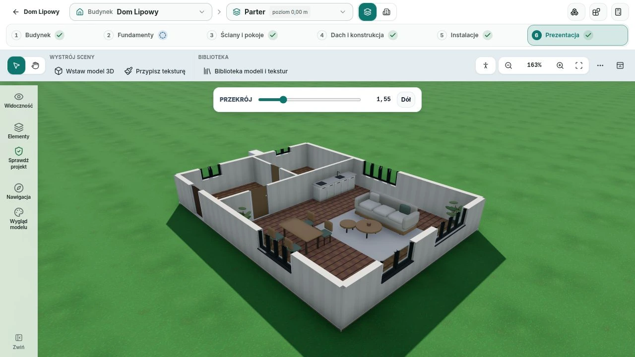
Switch to 3D, rotate the building and select a floor. Check openings, heights and room layouts. Return to the floor plan to correct anything that looks wrong.
The plan and 3D view show the same model. Changing a wall affects its geometry and quantities. Use the model to plan work; structural decisions still need suitable design documents and professional checks.
Check before the next step
- Compare at least two dimensions with the source drawing.
- Check the floor, heights and openings.
- Wait for changes to save before closing the project.
Step-by-step exercise
Prepare one floor and check it in 3D
What you will do
Save a scaled underlay, a simple outline, a partition and an opening. Check the same layout in 2D and 3D and identify the rooms in the project.
Practice example
Use a practice project, such as “Ground floor renovation — practice”. Choose a simple drawing with at least two known dimensions. Work on an area with reliable documentation rather than changing an agreed customer project.
Prepare before you start
- A project with a building and floor, and permission to edit the drawing. Creating a project also requires project creation access.
- A JPG, PNG or WebP image, or a PDF drawing with a known distance in metres. Adding an underlay needs file permissions and available storage.
- A browser with an internet connection. A larger screen is convenient for a first attempt; a separate exercise covers phone use.
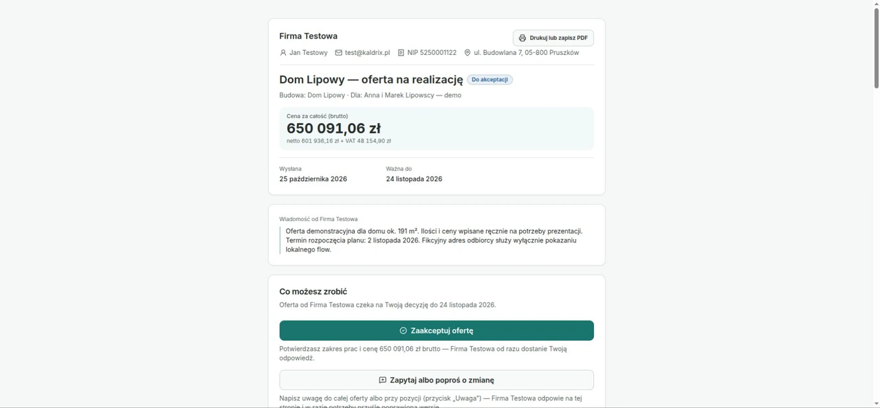
In the print window, choose Save as PDF if your browser provides that option. Check the page preview before saving.
Follow these steps
Open the drawing for the right floor
- Open the project and Drawing. Check the building and floor in the header.
- Choose 2D. Note the floor name so you can compare the same level in the model later.
Expected result: The header shows your chosen building and floor, and the drawing is in 2D.
If you get stuck
If you can only view, check “Drawing and building model: Changes” and whether the project allows saving. Access to a project alone does not grant editing permission.
Load the correct drawing page
- Open Floor plan underlay and add an image or PDF.
- For a PDF, wait for page preparation and select the page for this floor. Adjust rotation and transparency so lines are clear.
Expected result: A readable underlay is assigned to the correct floor. It is still an image, without created walls.
If you get stuck
If the PDF does not prepare, read the message and check the page and file limit. You can prepare the required page as a PNG. Avoid adding repeated copies of the same file.
Set the scale and check another dimension
- Choose Fit measurement, mark both ends of a known distance and enter its length in metres. For 366 cm, enter 3.66.
- Choose Save alignment. Use a quick measurement on a different known distance and compare it with the source drawing.
Expected result: The second distance agrees closely enough with the source to trace the scope reliably. The underlay adjustment is saved.
If you get stuck
If the second result differs noticeably, check the endpoints, unit and PDF page. Repeat the adjustment using a longer known distance. Rotating an image does not correct its scale.
Set the building shape
- In the Building stage, match the floor outline to the checked underlay. Check external dimensions rather than judging only by appearance.
- Enable the dimensions and names you need in View → Visibility. Check a simple shape before adding more complex sections.
Expected result: The outline matches the practice area. It creates perimeter walls and the floor and ceiling surfaces for the storey.
If you get stuck
If the outside shape is wrong, return to the outline in the Building stage. Renaming a room does not change the outline or create a wall.
Add one partition and name the rooms
- Go to Walls and rooms. In + Add, choose Wall and draw a partition between the appropriate walls.
- Return to Select / edit. Check wall thickness and height, and give the resulting rooms clear names.
Expected result: A closed partition divides the interior into identifiable rooms. You can check their names and areas on the plan.
If you get stuck
If rooms are not divided, zoom in on both partition ends and check connections. Do not try to fix this by adding overlapping walls.
Insert a door and check its size
- Choose Wall opening, set the type to Door and select the correct wall.
- Switch to Select / edit, select the door and enter the documented width and height. Check its position and opening direction where the chosen variant supports them.
Expected result: The door is in the chosen wall with checked dimensions. Further clicks in selection mode do not insert more doors.
If you get stuck
If more openings appear, finish the tool and return to selection. If an opening does not fit, check its wall, position and size instead of shrinking it merely to remove an error.
Check the project and inspect the same level in 3D
- Open the project check panel and read reported problems. Correct those relevant to your practice area.
- Switch to 3D and choose the same floor. Inspect heights, the partition and the opening. Wait for saving, then reopen the drawing.
Expected result: You recognise the floor plan layout in 3D, and the changes remain after reopening.
If you get stuck
If an element is missing, check the selected floor and visibility settings. The 3D view is not a separate project copy. Verify structural decisions using suitable documents and qualified advice.
Check your work
- You can identify two checked dimensions and the saved underlay scale.
- The same floor contains a partition, an opening and clearly named rooms.
- Changes are saved and remain visible after reopening.
Common obstacles
The drawing looks right, but quantities seem too large or small.
Check underlay scale and drawn element dimensions separately. An image does not create geometry: a correctly scaled underlay does not repair walls drawn with wrong dimensions earlier.
The drawing no longer matches after changing the PDF page.
Position and scale may remain from the previous page. If pages use different scales, repeat dimension fitting for the current drawing and save the setting.
A message says the model changed while you were working.
Read the message and compare the current model before editing again. Adding the wall again may not restore the right state; first check what has already been saved.
Next exercise: Model quantities and floor plan measurements: what to check →